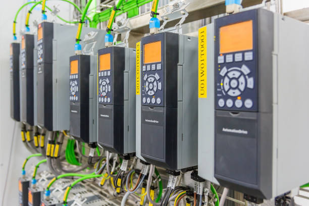
Motor drives, commonly known as Variable Frequency Drives (VFDs), have become indispensable across industries. From process automation and fluid pumping to HVAC and robotics systems. Their ability to control motor speed, torque, and energy consumption makes them applicable in various industrial needs. However, proper configuration based on manufacturer specifications is critical for efficiency, protection, and longevity.
Core Architecture of a Motor Drive
Rectifier Stage – Converts the AC supply to DC. Always ensure supply voltage compatibility. Installer needs to understand the drive voltage input before connecting because an overvoltage may damage drive components. for instance plugging in a 400v power to a 240v input results to damage.
DC Link – Smooths the DC voltage through capacitors and inductors. Excessive harmonics or unstable input supply can contribute to DC bus voltage fluctuations, and in applications where braking resistors are undersized, this may lead to overvoltage faults.
Inverter Stage – Uses IGBTs (Insulated Gate Bipolar Transistors) to convert DC into a variable-frequency AC waveform. This is the heart of the drive’s torque and speed control system.
Control Unit – Manages all drive logic, including motor control modes (V/f, vector, or torque control), PID loops, and safety functions like Safe Torque Off (STO).
Siemens and ABB drives include advanced control modes such as sensorless vector control, enabling precise performance even without feedback encoders.
User Interface (HMI/Software) – Modern drives integrate digital operator panels and PC-based tools such as:
- Siemens STARTER / TIA Portal for SINAMICS configuration
- Schneider SoMove for Altivar drives
- ABB Drive Composer for ACS/ACH series
These tools simplify commissioning through guided setup wizards and real-time parameter monitoring.
Installation and Environmental Considerations
Mounting:
All three manufacturers emphasize correct enclosure class (IP rating) and spacing for heat dissipation. A clearance of 10–15 cm around heatsink vents ensures proper airflow. Drives such as the ABB ACS580 or Schneider Altivar 320 require derating when installed in sealed panels or high-altitude environments.
Wiring and EMC Compliance:
Shielded motor cables and proper grounding are mandatory. Siemens recommends 360° shield termination at both ends to reduce electromagnetic interference, while Schneider advises using ferrite cores for long cable runs.
Protection Devices:
Upstream circuit breakers or fuses must comply with the manufacturer’s short-circuit withstand limits (I²t values). Always consult the datasheet — Siemens, for example, lists permissible fuse ratings under its “Technical Data” section.
Key Configuration Parameters
1. Motor Nameplate Data
Input exact rated voltage, current, frequency, power factor, and speed.
In Siemens SINAMICS or ABB ACS drives, this data is critical for the internal motor model used in vector control. Incorrect entries lead to torque instability and overheating.
2. Ramp Times (Acceleration/Deceleration)
Set ramp times according to load inertia:
- Pumps/Fans – 10–20 s to prevent hydraulic shocks.
- Conveyors/Compressors – 3–5 s for faster response.
Schneider’s Altivar series includes an Automatic Adaptation function that tunes ramp profiles based on load feedback.
3. Frequency Limits
Define minimum and maximum frequency values. For example, limiting the top speed to 50 Hz on a fan prevents overcurrent trips in light-load conditions.
4. Control Mode Selection
- V/f Control: Simple, suited for constant-torque loads such as pumps and fans.
- Vector Control: Offers precise torque and speed response, ideal for cranes, mixers, and hoists.
ABB’s ACS580 automatically identifies motor parameters through ID Run, optimizing performance.
5. PID and Application-Specific Settings
Integrated PID controllers in ABB and Schneider drives allow direct control of pressure, temperature, or flow without external PLCs. Technicians should tune PID gains carefully to prevent oscillations.
6. Protection and Fault Handling
Enable thermal overload, under/overvoltage, and motor stall protections. Siemens drives support configurable fault reactions — for example, “ramp-to-stop” or “coast-to-stop” depending on system needs.
Commissioning Checks
Before commissioning, always confirm that parameters entered in the drive match the motor’s nameplate and that protective functions are enabled. Verifying ventilation, cable shielding, and proper grounding ensures the drive operates within its thermal and electromagnetic limits. This careful approach extends service life and prevents costly downtime. Majority motor-drive manufacturers provide comprehensive technical documentation and configuration tools to assist technicians. Always:
- Match the drive’s voltage and current ratings with the motor and power supply.
- Verify wiring, grounding, and environmental conditions.
- Enter motor parameters precisely and tune acceleration, deceleration, and protection settings.
If you are ever uncertain during installation or programming, consult the official datasheets or seek professional assistance. Proper configuration ensures safety, reliability, and optimal performance throughout the drive’s lifetime.